PCB assembly for UCLA 2P Miniscope
From Miniscope
Guide · 16 June 2026
FlexPCB for UCLA 2P Miniscope
1. Prepare electronic components
| null | Sourced | Placed | References | Value | Footprint | Quantity |
|---|---|---|---|---|---|---|
| 1 | C1 | 4.7uF | C_00402_1005Metric | 1 | ||
| 2 | C2 | 0.1uF | C_00402_1005Metric | 1 | ||
| 3 | C3 | 100nF | 100V | C_0603_1608Metric | 1 | |
| 4 | R2, R3 | 1.8k | R_0402_1005Metric | 2 | ||
| 6 | L1 | 3.3uH | L_0603_1608Metric | 1 | ||
| 8 | D2 | D | D_SOD-323_HandSoldering | 1 | ||
| 9 | U1 | MEMS_2.0 | PLCC-20_Mirrorcle | 1 | ||
| 10 | U2 | MAX14574EWL+ | BGA_15 | 1 |
2. Reflow soldering Solder paste (SMD291AX10T5, DigiKey Part Number: SMD291AX10T5-ND). Soldering setup: follow the solder paste instructions
- Check Flex_PCB under scope for potential defects
- 2D MEMS scanner is mounted on the back side first
- All the others are mounted on the top side (Cautions: C2&C3 have different footprint)
- U2 orientation marker is wrong (the opposite corner of "+")

3. Prepare cables
- CABLE MICRO COAXIAL 42 AWG 100' (DigiKey Part Number: MTF1022-100-ND)
- 36 Wire Gauge Wire with Silicone insulation (Mcmaster Carr: 9564T1)
- 10 position flat ribbon cable with socket-to-socket plug (DigiKey Part Number: 952-2568-ND)
Cautions:
- Remember to label the wires after stripping.
- Use thermal shrink tubes to protect the soldering connections.
- Use UV glue (Thorlab: NOA68) to seal electronics after soldering


4. Electrical inspection
- Electrical connection between 10 position socket and flex_PCB (with mini2p interface PCB testing board)
- Apply XY waveform to test the scanner
5. 3D printing the mini2p assembly (MyDrive\mini2p\3D printing parts)
- Painting & cleaning
- Following "UCLA 2P Miniscope Assembly Guide.docx"
6. Hollow fiber preparation
- Fiber-end glass cap (ask Blake for the printing model)
- Ream the cap with 1.8 mm reamer (Mcmaster Carr: 8803A156 )
- Mount #0 coverslip (3 mm diameter, Warner Instruments, order number: 64-0726, model number: CS-3R-0). Caution:UV glue NOA68 (glass to plastic), not the NOA61(glass to metal).
- Prepare fiber in the same length of cables (Hollow core photonic crystal fibers: HC-920-PM)
Cautions: optical fiber will generate dispersion and broaden the pulse width!!! To calculate the pulse width by fiber length, following the instruction: Supplementary Note 1: Optimizing femtosecond pulse delivery using the HC-920 (ref: 1. W. Zong, et. al. Fast high-resolution miniature two-photon microscopy for brain imaging in freely behaving mice. Nat. Methods. 14, 713–719 (2017).) - Cut fiber and mount fiber ferrule
- Fiber cleaver CT-101 (with fiber holder FH-250)
- Ferrule (# FER-1.8-127-ZR-NS-6)
Cautions: the fiber end should extend out of the ferrule a little bit, to protect the open-end, put the glass cap after mounting the ferrule.
- Fiber alignment with laser source
Figure 3. The fiber end alignment setup 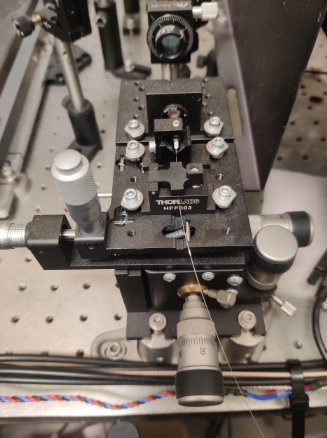
- Axial position adjustment of the fiber ferrule within the collimator.

- Carefully adjusting the distance between the end of the fiber (stuck to the fiber ferrule) and the collimating lens (stuck to the collimator house). Monitoring continuously the laser beam with the NIR detector card (Thorlab, part number: VRC4) until the center spot remains unchanged within a long distance.
- Firmly attaching the ferrule to the collimator house with the UV-Curing optical adhesive.
7. Connect SiPM cables
- CABLE MICRO COAXIAL 42 AWG 100' (DigiKey Part Number: MTF1022-100-ND)
- SMA connector plug male pin board edge (DigiKey part Number: 732-13857-ND)
- Cable2SMA board (https://oshpark.com)
Cautions:
- 2 Coax cables for each SiPM detector, short connect the shielding layer and solder a connector for GND plug-in.
- Based on "UCLA mini2p interface board" design, the outside thread is connected to Anode of SiPM; the inner pin is connected to Cathode of SiPM.

8. MEMS details
- A7M20.2-2000AL in the 2mm diameter LCC20 ceramic package
MEMS mirrors it's $499 + $290 each times qty plus $950 lot fee. Driver pricing is $750 for 1 (qty), $690 for 2-4 (qty) and $590 for 5-9 (qty) orders. Mandatory accessory is at least 1 (qty) breakout board ($89/each).