Guide/UCLA 2P Miniscope Assembly
UCLA 2P Miniscope Assembly Guide
You’ve decided to assemble a UCLA 2P Miniscope! That’s wonderful, and it is our sincere goal to help walk you through that process to make it as intuitive and straightforward as possible. This document will be updated over time following user feedback and serves as a constantly improving guide to constructing the microscope headpiece. We are still in early stages here, and we are hoping to make this open-source project as useful as possible. Please reach out to bmadruga@physics.ucla.edu and pgolshani@mednet.ucla.edu with any questions.
Table of Contents:
1. Collimator Assembly
2. Lower Housing Assembly
3. Detector Assembly
4. Main Housing Assembly
The necessary tools for assembling the microscope are:
| Component | Part Number | Manufacturer | Unit | Price | Subtotal | Link |
|---|---|---|---|---|---|---|
| UV-Curing Gun | LED-200 | Electro-Lite | 1 | $1,932.00 | $1,932.00 | UV-Curing Gun |
| Flathead Driver | 84705260150 | Wiha | 1 | $5.17 | $5.17 | Flathead Driver |
| Torx Screwdriver | 52995A24 | McMaster-Carr | 1 | $9.48 | $9.48 | Torx Driver |
| Scan Lens Reamer | 8851A18 | McMaster-Carr | 1 | $24.18 | $24.18 | Scan Lens Reamer |
| Tube Lens Reamer | 8851A21 | McMaster-Carr | 1 | $28.78 | $28.78 | Tube Lens Reamer |
| Collection Lens Reamer | 8851A17 | McMaster-Carr | 1 | $23.63 | $23.63 | Collection Lens Reamer |
| NIR Viewing Card | VRC4 | ThorLabs | 1 | $94.05 | $94.05 | NIR Viewing Card |
| Total | $2,234.26 |
These tools are what we use in the lab to assemble the microscope headpieces. There are certainly other alternatives or other approaches to building these microscopes. We are just providing what worked well for us.
Now that we confirmed that all of the necessary tools are present, we will break the microscope down into 4 subassemblies. First, we will build the simple subassemblies, then we will build the main housing and combine that main housing with the other subassemblies.
1. Collimator Assembly
The following components are required for the Collimator Assembly. Please verify that all components are sourced before beginning.
| Component | Part Number | Manufacturer | Unit | Price | Subtotal | Link |
|---|---|---|---|---|---|---|
| Collimator Housing | Collimator_Housing.STL | Custom | 1 | $1.00 | $1.00 | Collimator Housing |
| Collimation Asphere | KGA170-B | Newport | 1 | $107.00 | $107.00 | Collimation Asphere |
| ETL | A-25H1 | Varioptic | 1 | $135.00 | $135.00 | ETL |
| Torx Screws | 96817A704 | McMaster-Carr | 4 | $0.63 | $2.53 | Torx Screws |
| $245.53 |
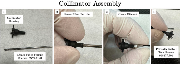
Building the Collimator consists of 10 steps in total.
- Collect Collimator Housing and 1.8mm Fiber Ferrule Reamer.
- Ream the fiber input to 1.8mm in order to tightly support the optical fiber ferrule.
- Check the fit of the ferrule in the housing using the input hollow core optical fiber. The goal is to ensure a snug fit with enough play to allow for axial positioning of the ferrule within the collimator housing. We will eventually ensure that the distance is optimal by checking the collimation of the light following the asphere.
- Partially install the torx screws, as this makes joining the collimator and main housing assemblies far easier down the road.
Collimator Assembly
- Prepare the collimation asphere and ensure that the directionality is correct based on the optical model and supplied figure. The more flat surface is oriented closest to the fiber input.
- Install asphere until pressed into the fixed stop in collimator housing.
- Add a small amount of NOA68 to one corner of the lens (minimize the amount of clear aperture obscured) and cure using a UV lamp.
- Install fiber ferrule that is aligned to the 2P laser and emit a small amount of laser power from the 2P laser (< 20mW).
- Check the collimation state of the laser after the asphere and modulate the axial position of the fiber ferrule within the collimator to optimize. The diameter of the laser beam should remain constant from the front surface of the asphere, to ideally, infinity. In our hands, we ensure minimal divergence over approximately 2 meters and it seems to produce expected results. To visualize the laser beam, we suggest using the VRC4 NIR viewing card from ThorLabs.
- Once divergence is minimized and the laser is well collimated, add a small amount of NOA68 to the interface of the collimator housing and the fiber ferrule to keep the fiber in the correct position.


2. Lower Housing Assembly
The following components are required for the Lower Housing Assembly. Please verify that all components are sourced before beginning.
| Component | Part Number | Manufacturer | Unit | Price | Subtotal | Link |
|---|---|---|---|---|---|---|
| Lower Housing | Lower_Housing.STL | Custom | 1 | $1.00 | $1.00 | Lower Housing |
| Objective Lens* | OT-2 (Custom) | Optics Technology | 1 | $4,000.00 | $4,000.00 | Objective Lens |
| O-Ring | McMaster-Carr | 1 | $0.1596 | $0.1596 | O-Ring | |
| * Tube lens is custom fabricated, please contact pgolshani@mednet.ucla.edu for more information | $4,001.16 | |||||
The lower housing can be built in only 3 steps.
- Collect all necessary components.
- Install O-Ring into the lower housing.
- Press the objective lens into the lower housing.

3. Detector Assembly
The following components are required for the Detector Assembly. Please verify that all components are sourced before beginning.
| Component | Part Number | Manufacturer | Unit | Price | Subtotal | Link |
|---|---|---|---|---|---|---|
| Detector Housing | Detector_Housing.STL | Custom | 1 | $1.00 | $1.00 | Detector Housing |
| Emission Filter Support | Emission_Filter_Support.STL | Custom | 1 | $1.00 | $1.00 | Emission Support |
| Collection Lens | 47-895 | Edmund Optics | 1 | $62.50 | $62.50 | Collection Lens |
| Emission Filter (Cut)* | ET750sp, 4mm OD x1mm | Chroma | 2 | $150.00 | $300.00 | Emission Filter |
| 1P Dichroic (Diced)** | T550lpxr, 4x4x1mm | Chroma | 1 | $112.50 | $112.50 | 1P Dichroic |
| SiPM Detector | S13360-3075PE | Hamamatsu | 2 | $52.88 | $105.76 | SiPM Detector |
|
$582.76 | |||||
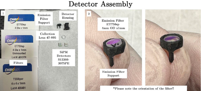
The Detector Assembly is constructed in 10 steps. The process involves putting together two components, the Emission Filter Support and the main Detector Housing.
- Collect all necessary components listed above.
- Install emission filter 1 into the emission filter support making sure of filter orientation.
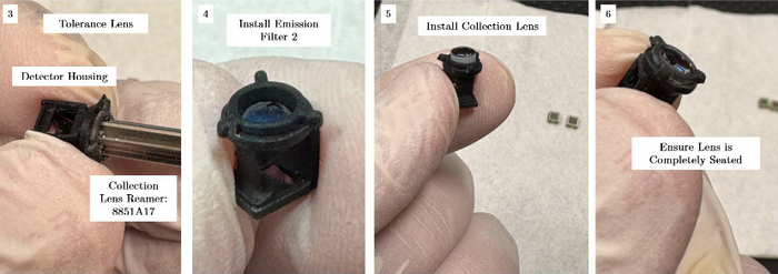
- Ream the detector housing using the collection lens reamer to ensure a secure fit. Take care not to ream excessively far as it will disrupt the mounting surface for the emission filter 2.
Collimator Assembly
- Install emission filter 2 making sure to orient the filter with the arrow oriented correctly.
- Install collection lens (orientation does not matter in this case).
- Ensure that the lens is fully seated in place, the lens should be nearly flush with the front of the detection housing.
Collimator Assembly
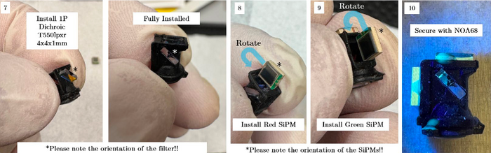
- Install the 1P dichroic mirror that splits the fluorescent signal between the two SiPM detectors. Make sure the arrowhead is pointing at the arrowhead printed into the detector housing. Make sure it's fully installed and supported on both sides of the housing.
- Install the first SiPM (red). The image shows the correct orientation of the SiPM, simply imagine rotating along the longer axis, like turning the page of a book.
- Install the second SiPM (green) in the same way as described in step 8.
- Fix the SiPMs and dichroic with very small amounts of NOA68.
Collimator Assembly


4. Main Housing Assembly
These components are required for the Main Housing Assembly. Please make sure everything is sourced before beginning.
| Component | Part Number | Manufacturer | Unit | Price | Subtotal | Link |
|---|---|---|---|---|---|---|
| Main Housing | Main_Housing.STL | Custom | 1 | $1.00 | $1.00 | Main Housing |
| Lens Cover | Lens_Cover.STL | Custom | 1 | $1.00 | $1.00 | Lens Cover |
| Flex-PCB | FLEX-PCB | Custom | 1 | $600.00 | $600.00 | Flex-PCB |
| Scan Lens | AC050-010-B | ThorLabs | 2 | $51.38 | $102.76 | Scan Lens |
| Tube Lens* | OT-1 (Custom) | Optics Technology | 1 | $1,100.00 | $1,100.00 | Tube Lens |
| 2P Dichroic (Diced) | ZT775sp-2p, 8x8.5x1mm | Chroma | 1 | $540.00 | $540.00 | 2P Dichroic |
| Torx Screws | 96817A704 | McMaster-Carr | 4 | $0.63 | $2.53 | Torx Screws |
| Optical Glue | NOA68 | Norland | 1 | $40.70 | $40.70 | Optical Glue |
| MEMS Scanner | A7M20.2-2000AL | Mirrorcle | 1 | $710.10 | $710.10 | MEMS Scanner |
| * Tube lens is custom fabricated, please contact pgolshani@mednet.ucla.edu for more information | $2,387.99 | |||||
This assembly is the most involved and requires 13 steps to build. Finally integrating with all the other assemblies takes another 10 steps.
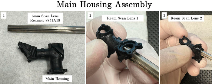
- Collect the main housing and the scan lens reamer.
- Ream the hole for scan lens 1. This process is to be done quite lightly by hand and is simply to ensure a snug fit between the housing and the scan lens doublet. There are internal stops in the main housing, so be mindful and only clean up the walls leading to the stop. In our experience this did not need to be completed in a highly accurate fashion.
- Ream the hole for scan lens 2 in the same way as in step 2.
Collimator Assembly
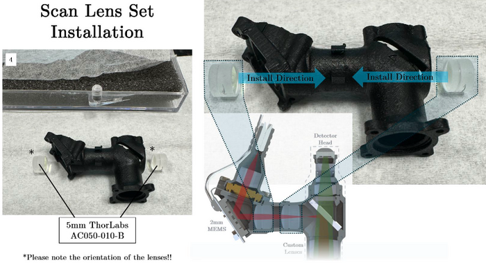
- Collect the scan lenses and ensure that the orientation of the lenses is correct. The crown glass for each scan lens should be positioned closest to the scanning mirror.
Collimator Assembly
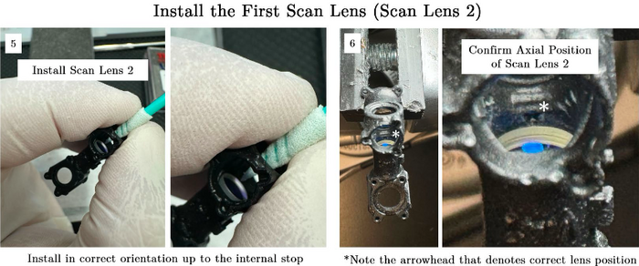
- Install scan lens #2 by pushing it through the front of the microscope, opposite the MEMS scanner surface. This can be a little tricky, so take your time and make sure the orientation is maintained. We repeatedly lightly press on opposing edges of the lens to coax it into place.
- Press the lens into the correct position using a non-abrasive implement. We use dust-free foam swabs from Amazon (pictured in the images below) ASIN no. B0CTQCGXP2. Once the lens is pressed into place, confirm location with the arrowheads that are fabricated into the microscope housing.
Collimator Assembly
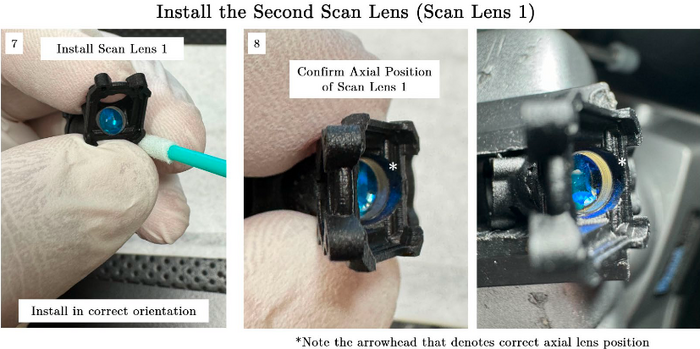
- Next, install scan lens #1 from the MEMS scanner side of the microscope using the same technique as in step 5.
- Confirm placement of scan lens #1 as in step 6.
Collimator Assembly
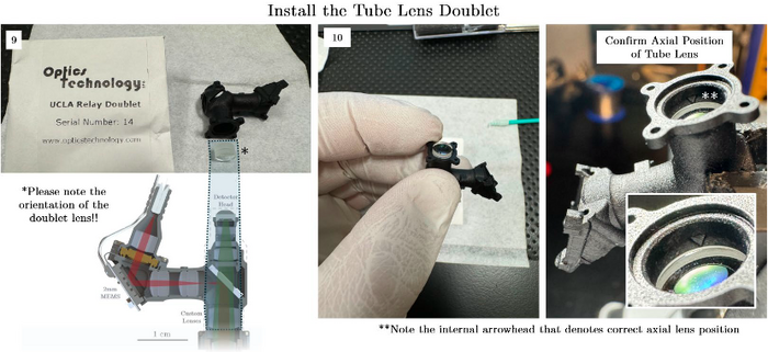
- Prepare the tube lens and ensure the orientation is consistent with the figure below. The crown glass is oriented towards the objective.
- Press the OT tube lens into place following steps 5 and 7 and check the axial position of the doublet as is done in steps 6 and 8. This time the arrowhead is more easily photographed for demonstration purposes.
Collimator Assembly
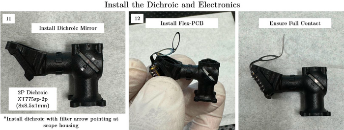
- Install the 2P dichroic mirror taking note of the arrow placed on the component by the manufacturer. Make sure it is going through both ends of the slot.
- Orient the Flex-PCB such that the scanning mirror is pressed up to the mounting surface present in the Main Housing. Ensure there is solid contact without gaps on any end between the LCC package of the scanner and the housing.
Collimator Assembly
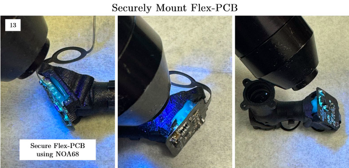
- Use NOA68 to fix the MEMS scanner to the main housing. We have had success fixing the sides and bottom surfaces.
Collimator Assembly
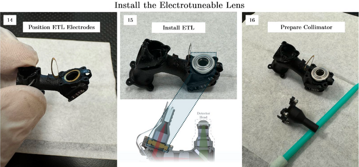
- Position the electrodes for the ETL once the Flex-PCB is secured in place. The main housing has built-in features that are designed to grip the ETL electrodes to hopefully make assembly a bit easier.
- Next, install the ETL by first placing it on the electrode in the correct orientation described in the figure below.
- Prepare the collimator to join the assembly. For this guide, we are demonstrating this assembly without the installed optical fiber. In reality this union of two parts needs to be done after the collimation was defined in the initial part of the assembly guide. This adds a slight complication but the overall technical process is the same.
Collimator Assembly
- Join the collimator and main housings. The way this is accomplished most successfully in our experience is to first fit the exposed remaining electrode into the collimator using tweezers, making sure to not scratch the asphere. We then can sandwich the ETL between the collimator and housing, making sure the electrodes are in the correct locations. Since the screws are already in place, we just need to use the torx driver to join the two assemblies. We suggest iteratively tightening screws in a sequential way to avoid excessive torque on any one screw. So lightly tighten all the screws first, then screw them all slightly more tight, until you have solid mechanical contact between the collimator and housing.
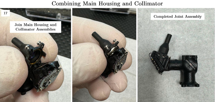
Collimator Assembly
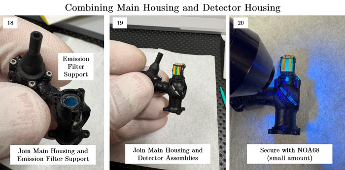
- Mount the emission filter support in place. There is a specific orientation that works best, which involves the long legs of the support resting on the 2P dichroic. Take a look at the mechanical drawings in the manuscript for more information.
- Install the main detector housing by pressing it into place. The housing should be a snug fit but uniformly bottomed-out against the main housing.
- Add two or three small applications of NOA68 to mechanically mate the detector and main housing. If correctly assembled, this is mainly for peace of mind rather than a required mechanical connection.
Collimator Assembly
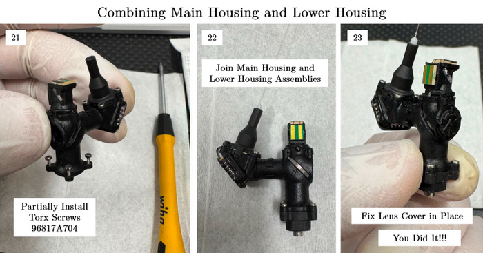
- Add the torx screws to the main housing in the same way as was done with the collimator.
- Join the main housing and the lower housing, pressing the objective into the correct place in the main housing by applying a small amount of force from the lower housing. Tighten the screws in the same way as was done with the collimator assembly.
- Add the lens cover in place and fix with a small amount of NOA68. And you’re DONE!
Collimator Assembly


