| [#62] |
Hello,
I have the DAQ box and Miniscope assembled, but when I plugged everything in to the computer for the first time I was met with the notification "USB Power Surge on USB Port" and "USB Port requires more power". When the DAQ box is plugged in the computer it powers on fine, but once the miniscope coax is connected to the box the power goes out and the notification pops up. Our computer has all the necessary specifications (USB 3.0, Windows 10). Has anyone encountered this issue?
I tried plugging in to the DC Jack on the DAQ to have that source of power but for some reason the cable will not plug in.
Thanks!
Cameron
Posted by Camwinslow98 on 24 June 2016 at 17:19.
Edited by Camwinslow98 on 24 June 2016 at 17:28. |
|
Sounds like you have a short on the miniscope coax. Either that or your USB port is bad and can't deliver the required current. Did you try with another PC? Do you have a lab power supply to power the CMOS sensor PCB separately from the rest of the system?
Not having the BOM at hand, I suspect the DC jack on the DAQ is 5.5mm with a 2.5mm pin. If you try to plug in a (very common) 5.5 / 2.1mm plug, the pin in the jack will be too big for the plug's hole.
| Posted by MikerVee on 24 June 2016 at 18:21. |
|
Posted by MikerVee on 24 June 2016 at 18:21. »Sounds like you have a short on the miniscope coax. Either that or your USB port is bad and can't deliver the required current. Did you try with another PC? Do you have a lab power supply to power the CMOS sensor PCB separately from the rest of the system?
Not having the BOM at hand, I suspect the DC jack on the DAQ is 5.5mm with a 2.5mm pin. If you try to plug in a (very common) 5.5 / 2.1mm plug, the pin in the jack will be too big for the plug's hole.«
This same thing is happening with multiple PC's except one of the desktop computers, but the DAQ box would heat up quickly when leaving it plugged in. The BOM does say that the jack is 5.5 mm x 6.3 mm so it makes sense that the plug I was trying to use did not fit as it was probably the common one that you suggested.
If I get a larger diameter plug, would it make sense to power the box with that DC cable while still connecting it to the USB port on the PC to connect to the software?
| Posted by Camwinslow98 on 24 June 2016 at 19:06. |
|
There is a jumper on the DAQ PCB that gives you the choice of powering from the USB port or from the DC jack. But if multiple PCs notify you of a USB power problem, and the DAQ heats up noticeably, I suspect you have a problem on the CMOS PCB. Better try figuring that out first instead of forcing things by injecting more current. The CMOS PCB does seem to draw a lot of current, as it gets quite hot under normal use. But never so much, in my experience, that the USB port complains. Did you check which component(s) on the DAQ PCB get hot after connecting the CMOS coax?
| Posted by MikerVee on 24 June 2016 at 19:19. |
|
When the board was first connected I could not find a specific component that was causing the issue.
However, I tried to connect to that PC that worked before to see if the box would get hot again, but it never did, and the computer recognized the miniscope right away as opposed to not recognizing it the first time. I also tried connecting it again to the original laptop that was obtained to do this project and there was no power surge notification, for one of the DAQ boxes at least. So for some reason one of the boxes works now, without the power surge notification. I have no idea what could have changed to enable this to work now, and I'm not so sure that it will be that reliable.
Another problem I'm faced with now is that the Data Link LED will not go on at all. It never has.
I apologize if this sounds a bit confusing.
| Posted by Camwinslow98 on 24 June 2016 at 20:05. |
|
Hi Camwinslow98,
It definitely sounds like the source of your issues is your coax cable connecting the DAQ PCB with the CMOS PCB. More specifically, it is likely the soldering of the ends of the coax cable to the PCBs has a short. You can use a multimeter to check for shorts on your coax cable. If one is present, you may or may not have permanently damaged your DAQ PCB. Once you check this, please update me and we can proceed with fixes.
The Data Link LED being off also suggests issues with improper soldering. Does the red LED on the CMOS PCB turn on when plugged in? Once assembled/soldered correctly, I can assure you that the Miniscope system is extremely stable and reliable.
Finally, where did you get your PCBs fabricated and assembled? If you were part of any of the Miniscope group PCB orders then it is highly unlikely the issue is anywhere other than the soldering of the coax cable.
| Posted by DAharoni (administrator) on 25 June 2016 at 04:46. |
|
So today I first checked for shorts on all the wires (coax wired onto the DAQ and coax going from the CMOS to the connector), and could not find any. Upon further inspection it seemed that the wiring for the signal and ground pins on the CMOS PCB was incorrect, for the smallest inner conductor was not connected to the Signal pin. We re-soldered that wiring as well as the wiring to the connector (for the CMOS coax), as well as creating a new DAQ PCB, and now the red LED turns on on top of the CMOS PCB, but the Data Link LED still will not turn on. We're a step further in the right direction though.
After redoing all of those parts we do not get the initial "USB Power Surge" notification that we saw before.
| Posted by Camwinslow98 on 27 June 2016 at 19:14. |
|
Hi Camwinslow98,
This is definitely great progress.
- The red LED being on means the scope is receiving power over the coax cable.
- The Data Link LED being off means one of two things:
- That the higher frequency imaging communication is failing over the coax cable.
- or that either the CMOS sensor, serialize, or deserialize are not functioning properly. (unlikely)
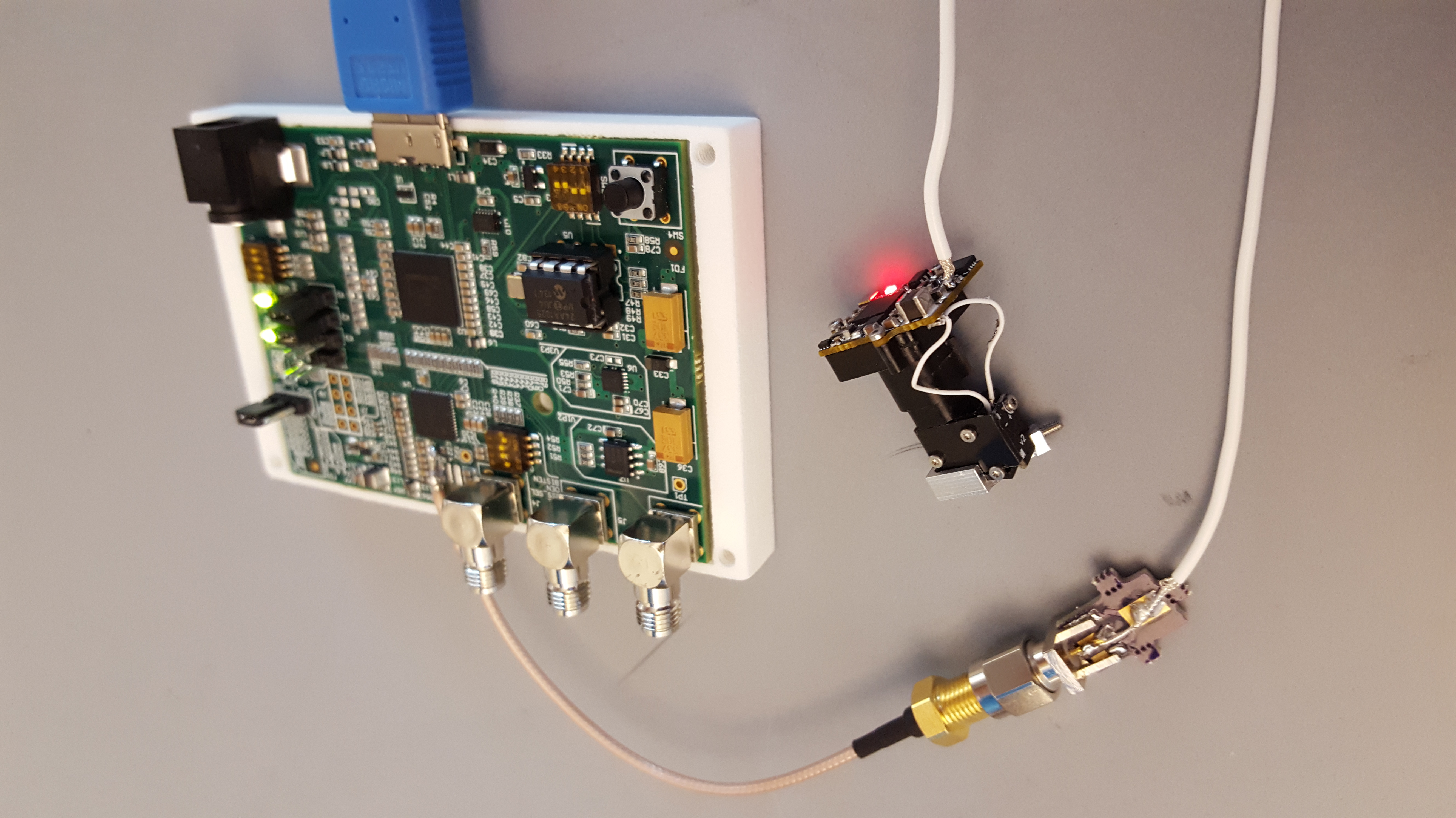
It is very likely that the source of the issue is still with the coax cable and soldering. What coax cable are you using? How long is it? What type of coax cable connectors are you using? Can you upload a picture of your system?
| Posted by DAharoni (administrator) on 28 June 2016 at 17:05. |
|
I'm using the Cooner Wire, about 3.5 ft long. For connectors I have the Edge Mount SMA Connector used with the PCB from OSH Park. These should all be the recommended parts for this assembly. What's the best way to upload a photo? I tried but there was an error with the thumbnail I guess and wouldn't show up in the forum.
Thanks for your help!
| Posted by Camwinslow98 on 28 June 2016 at 17:53. |
|
http://miniscope.org/images/2/2e/20160628_134130.jpg
Maybe this link works...
| Posted by Camwinslow98 on 28 June 2016 at 17:58. |
|
I just used a new CMOS sensor and soldered the coax to it, and I am positive that the soldering is correct. Still no Data Link LED. Red light is still on though.
| Posted by Camwinslow98 on 29 June 2016 at 13:48. |
|