System Assembly
This guide will take you through the assembly of the entire miniscope system.
Contents
Head Mounted Scope Assembly
A brief outline of steps to assemble the scope can get found here: File:AssemblingScope.pdf.
Lens Installation
Filter Set Installation
Excitation PCB Installation
CMOS Imaging Sensor PCB Installation
Data Acquisition System Assembly
We generally have all surface mount (SMD) components assembled on the DAQ PCB by a third party PCB assembly house leaving only the through-hole components to be assembled in lab. It is possible to have the assembly house place both SMD and through-hole components but it is more expensive and through-hole components are relatively easy to solder. A good through-hole soldering tutorial can be found here.
Through-hole component assembly
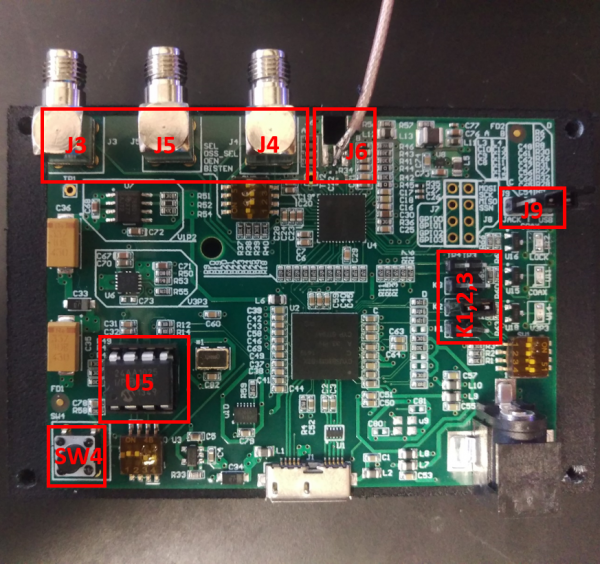
If you decide to have the through-hole components assembled by an assembly house you can skip this section. Below is a picture highlighting the necessary through-hole components that need to be soldered in order for the DAQ PCB to function properly.
- Description of components
- SW4: Reset button the resets can reset the USB Host Controller
- U5: EEPROM (memory that holds the DAQ firmware) socket. You can also solder the EEPROM IC directly to the board but I prefer using an IC socket so I can swap out the EEPROM if necessary
- K1,2,3: Each are 2pin 0.1" headers
- J9: A 3pin header used with a 2pin jumper to select power source for the microscope
- J3,4,5: SMA connectors used for GPIO pins
- J6: We currently solder a short coax cable with SMA connector to these pads. This will be updated soon to a replace this with a proper PCB footprint
