Imaging With Thin GRIN Lenses
Want to image with thin GRIN lenses? Follow the simple steps below for modifying your scope to be able to image through 1mm diameter and thinner GRIN relay lenses. Also make sure you have read our GRIN Lens Information page.
Contents
Modification Overview
The Miniscope relies on a 0.25pitch, 2mm or 1.8mm diameter, objective GRIN lens for imaging. This lens can be implanted directly into the brain (Surgery Protocol, Surgery and Baseplating Presentation) but it can also be mounted into the scope to allow for imaging through thinner diameter GRIN relay lenses. A GRIN relay lens generates an intermediate image plane with close to unity magnification. The mounted 0.25pitch objected GRIN lens then images the intermediate image plane and forms a second image plane on the surface of the CMOS imaging sensor. Thanks to Eyal Kimchi at MIT for the initial design of this modification.
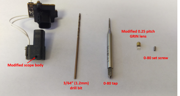
Miniscope Body Modification
In order to image thin GRIN relay lenses you will need to mount a 0.25pitch objective GRIN lens into the base of your Miniscope. While you could just glue in the lens to the main body of the scope, we prefer using a set screw so the objective lens can be easily removed.
- Step 1: Carefully drill (3/64" bit) a hole on the back side of the main body of the scope. Place the hole as close to the bottom of the scope as possible, making sure to avoid hitting the slot that holds the dichroic mirror. The hole should be aligned with the opening for the GRIN lens.
- Step 2: Tap the newly created hole with a 0-80 tap. This should be done by hand, making sure not to strip the plastic as it is being threaded.
GRIN Lens Modification
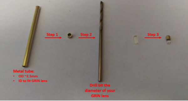
The opening for a GRIN lens in the bottom of the scope is 2.5mm in diameter. Adding a 2.5mm OD protective sleeve around the objective GRIN lens with protect the lens from the set screw as well as align it in the bottom of the scope. K&S 9833 Thin Wall Brass Tube (2.5mm OD x .225mm Wall) works well with 2mm diameter GRIN lenses. This precision miniature stainless steel tubing works well with 1.8mm diameter GRIN lenses.
- Step 1: Use a dremel or jeweler's saw to cut a metal or plastic tube 2mm to 3mm long. File or grind the ends smooth.
- Step 2: Use a drill bit or rod the diameter of the objective GRIN lens to ream out the inside of the tube and clear out any burrs that might have been created during cutting.
- Step 3: Glue or epoxy (do not use super glue due to out gassing) the tube around the objective GRIN lens. We generally apply a thin layer of optical glue around the side of the lens and then slide on the tube. Try to leave only ~0.5mm of exposed lens on the side that will be placed into the scope body. The protective tube can extend all the way to the bottom of the lens or can be left shorter. Care must be taken not to get glue on the top or bottom surface of the lens. Check these surfaces under a stereoscope and clean off any glue with filter paper and ethanol.
Implant and Imaging
A nice overview of imaging with a relay GRIN lens + objective GRIN lens can be found in this Nature Protocols paper by Resendez et al. While the approach outlined in this paper is centered around the commercial nVista system from Inscopix, it is directly applicable to our modified Miniscope system with mounted 0.25 pitch objective GRIN lens.
Our Surgery Protocol and Surgery and Baseplating Presentation focus on how to direct implanting the 0.25pitch objective GRIN lens but the approach outlined in these links is also directly applicable to implanting and imaging thin GRIN relay lenses.


