Initial Testing of Assembled Miniscopes
This page is a work in progress.
Once your Miniscope system is up and running, it is important to be able to test, and debug, all aspects of the system before moving to imaging in vivo. The sections below will discuss the procedures we use to validate Miniscopes we build before using them in experiments. As you become more comfortable with using Miniscopes some of the sections below can be skipped.
Contents
Testing the Coaxial Cable Connection
In our experience, the connection of the coax cable, either to the CMOS Imaging Sensor PCB or SMA connector, is by far the most common point of failure when building a Miniscope System. Take care when soldering these connections not to short the inner conductor to the outer shield. It helps to cover the solder joint as well as ~1cm of coax cable extending from the solder join in a semi-flexible epoxy, silicone, or glue (hot glue works well) to take the strain of cable movement off of the solder joint.
Once assembled, connect the Miniscope system to your computer and run the DAQ software. With the video streaming from the scope, move/twist/wiggle the coax cable with greater intensity that what you would expect an animal to apply, especially at the ends of the cable. If soldered correctly, the video stream should not drop out even with excessive movement and twisting of the cable.
Testing the Stability of the DAQ Software
Imaging Your Surroundings
Checking for Light Leakage
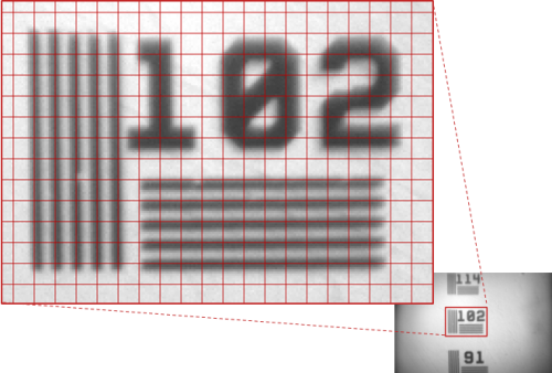
Imaging Calibration Slides
Imaging GFP Slides
Similar to imaging test slides, you can use your Miniscope to image brain slice slides expressing GFP or slides with other fluorescent sources. A few key points for imaging slides are listed below:
- Your scope has a green bandpass filter (500nm to 550nm) in front the the CMOS imaging sensor. This means only will only be able to see green fluorescence.
- Take note of the thickness of your cover slip, usually around 170um thick. You will be imaging through the cover slip to reach the fluorescing sample. If you are using less than a 15mm focal length achromatic lens, you will likely not be able to focus past the bottom of the cover slip. Even a 15mm focal length achromatic lens will generally just reach about 50um below the bottom of the cover slip with the focusing slider pushed to its lowest position.
The video to the left is of a TetTag GFP slide being imaged with a 15mm focal length achromatic lens and 0.25 pitch GRIN lens. Their are some compression artifacts present due to YouTube's compression of the video. The disk of light near the center of the field of view is due to reflection of the fluorescent light between the cover slip and bottom of GRIN lens... you should not see this disk when imaging in vivo.
