Microscope Components v1
Here we will discuss the different components that go into making up our microscope. This page will give a general overview of the system as well as a detailed description of assembly.

Contents
Scope Body
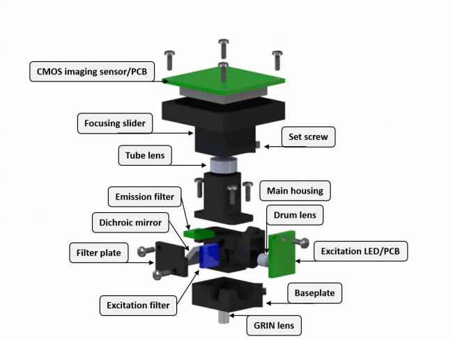
The microscope body is made out of 5 machined pieces of Delrin plastic. These components are a main body, fliter cover, two part focusing mechanism, and base plate.
Main Body
This is the center piece of the microscope and holds the excitation filter, dichroic mirror, and drum lens.
Filter Cover
This thin cover holds the excitation filter and dichroic mirror in place in the main body.
Focusing Mechanism
Adjustment of the imaging plane is accomplished by moving the CMOS imaging sensor along the z-axis. The two part focusing mechanism consists of a fixed tube and a focusing slider. The fixed tube holds an achormatic tube lens and proves a railing for the focusing slider to move along. The CMOS imaging sensor is attached to the top of the focusing slider and can be locked in place along the fixed tube with the use of a set screw.
Base Plate
The base plate gets cemented to the animal's skull and allows easy attachment and removal of the microscope. The microscope and the base plate have 3 matching pairs of magnets which snap the microscope in the correct position in the base plate. A set screw on the base plate is then used to secure the microscope.
Optics
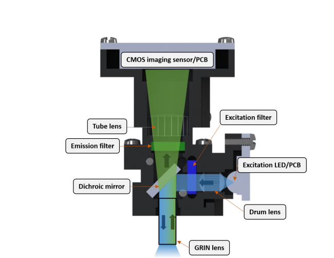
The optics of our microscope are very similar to a standard tabletop wide-field microscope. Excitation light is generated by a superbright LED, filtered by an excitation filter, and reflected by a dichroic mirror into a GRIN objective. Emission light travels through the objective and dichroic mirror and then filtered by an emission filter. The filtered light gets focused by an achromatic tube lens onto a CMOS imaging sensor.
Cable
Data, communication, and power lines are housed in a handmade, 8 line cable. This cable must be lightweight and extremely flexible while still handling the high bandwidth of the microscope's data lines.
CMOS Imaging Sensor PCB
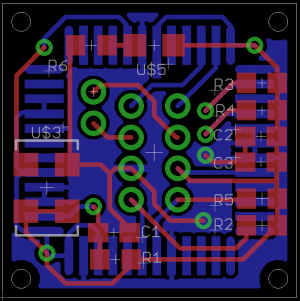
The CMOS imaging sensor is mounted on a 0.031" FR4 pcb along with a 26MHz clock and accompanying resistors and capacitors.

