Difference between revisions of "Head Mounted Scope"
(→Overview) |
Thebesteagle (talk | contribs) m (→Overview) |
||
| (50 intermediate revisions by 5 users not shown) | |||
| Line 1: | Line 1: | ||
| + | [[File:OverviewScope.png|thumb||600px]] | ||
| + | |||
| + | |||
| + | |||
| + | |||
== Overview == | == Overview == | ||
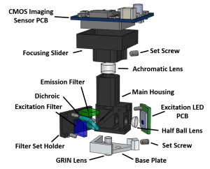
[[File:MiniscopeExplodedLabled.PNG|thumb|right|300px|Exploded view of the head mounted scope.]] | [[File:MiniscopeExplodedLabled.PNG|thumb|right|300px|Exploded view of the head mounted scope.]] | ||
| − | The head mounted scope consists of a machined Delrin housing, optical filters and lenses, an excitation light source, and CMOS imaging sensor. The mass of the system | + | The head mounted scope consists of a machined Delrin housing, optical filters and lenses, an excitation light source, and CMOS imaging sensor. The mass of the system is under 3 grams and connected to the DAQ hardware using a single coaxial cable. The body and optical components can be easily hand assembled using only forceps and a torx T2 driver. Optical filters are slid in from the side of the scope and held in place with a filter cover plate. The excitation half sphere lens sits in a spherical cutout and held in place by pressure from the LED PCB (optical glue is optional). The achromatic lens is slid through the top emission hole and either press fit into place or optical glued. |
| + | |||
| + | Adjustment of focal plane is achieved through adjusting the distance between the CMOS imaging sensor and other optical elements. The CMOS imaging sensor is mounted onto a sliding focusing mechanism which is moved by hand and locked in place with a 00-80 setscrew. Roughly speaking, movement of about 5mm of the CMOS imaging sensor results in a focal plane change of ~150um. | ||
| + | |||
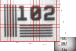
[[File:MiniscopeCalibrationSlide.png|thumb|left|300px|Image of a calibration slide with 9.8μm line spacing (superimposed red boxes are 10px x 10px)]] | [[File:MiniscopeCalibrationSlide.png|thumb|left|300px|Image of a calibration slide with 9.8μm line spacing (superimposed red boxes are 10px x 10px)]] | ||
The scope attaches to the head of the animal with the use of a small aluminum baseplate. The baseplate and scope have a matching set of 3 rare-earth magnets which helps with mounting the scope on an awake animal. Once the scope is in place a 00-80 set screw is used to fix it in place. | The scope attaches to the head of the animal with the use of a small aluminum baseplate. The baseplate and scope have a matching set of 3 rare-earth magnets which helps with mounting the scope on an awake animal. Once the scope is in place a 00-80 set screw is used to fix it in place. | ||
| + | |||
| + | |||
| + | <br clear=all> | ||
== Optical Path == | == Optical Path == | ||
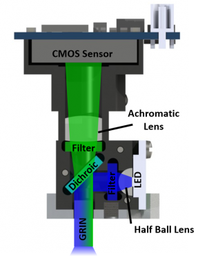
| + | [[File:MiniscopeOpticalPath.png|thumb|300px|Cross section of scope. Excitation path is in blue. Emission path is in green.]] | ||
| + | The optical path of the miniature microscope is very similar to a tabletop wide-field fluorescence microscope. The main difference is the size of the optical elements and the use of a GRIN lens as an objective. A more detailed discussion on GRIN lenses can be found [[GRIN Lens Information|here]]. | ||
| + | |||
| + | The optics in the miniscope use off the shelf lenses and diced commercial filters. Excitation light generated by an LED passes through a half-ball lens to help collimate the light | ||
| + | which is then bandpassed through an excitation filter and reflected using a dichroic mirror. | ||
| + | |||
| + | Emission light exits the objective GRIN lens in roughly a parallel orientation, passes through the dichroic mirror and then bandpassed through an emission filter. The light is then focused onto the CMOS imaging sensor using an achromatic lens. | ||
| − | + | <br clear=all> | |
== Machined Delrin Housing == | == Machined Delrin Housing == | ||
| + | The housing of the miniature microscope is machined out of plastic (we suggest using Delrin) and consists of a main body, filter set holder, and focusing slider. | ||
| + | <br clear=all> | ||
| + | |||
== Aluminum Baseplate == | == Aluminum Baseplate == | ||
| − | = | + | The baseplate is cemented to the animal's skull and provides the interface for temporarily connecting the miniature microscope to the animal. Three pairs of magnets on the baseplate and bottom of the microscope help snap the microscope in place and aid in placement when working with awake, freely moving animals. Once the microscope is placed in the baseplate, a 00-80 setscrew locks the scope in place. The setscrew applies a force along both sides of the scope making the mount very stable. |
| + | |||
| + | <br clear=all> | ||
| + | |||
== CMOS Imaging Sensor PCB == | == CMOS Imaging Sensor PCB == | ||
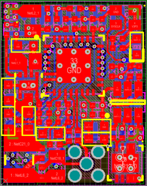
| + | [[File:CMOSPCB_1.png|thumb|300px|PCB layout of the CMOS imaging sensor PCB. The PCB is 13mm wide and should be printed on a 0.031" circuit board.]] | ||
| + | The CMOS imaging sensor PCB holds all the electronics needed to power and control the CMOS imaging sensor and excitation LED. A list of circuit features and components are listed below | ||
| + | *Power over coax filter to separate data/control stream from DC power. | ||
| + | *3.3V and 1.8V power regulators. | ||
| + | *Red LED shows board is powered properly and can be used for animal tracking. | ||
| + | *Serializer interfaces with imaging sensor and packages data to be sent over coax. | ||
| + | *A Digital to Analog Converter (DAC) and constant current source are used to control and power the excitation LED. | ||
| + | |||
| + | [[File:CMOSSchematic.png|thumb|left|500px|Schematic of CMOS imaging sensor PCB.]] | ||
| + | <br clear=all> | ||
| + | |||
| + | == Coaxial Cabling == | ||
| + | [[File:CoaxFPDLink.png|thumb|300px]] | ||
| + | The head mounted scope is connected to the DAQ hardware through a single, lightweight coaxial (coax) cable. | ||
| + | |||
| + | '''50Ω Coaxial Cable Features''' | ||
| + | *Power over coax + control signals + data + GPO | ||
| + | *Down to 0.3mm diameter | ||
| + | *Up to 15m long | ||
| + | *Commutator compatible | ||
| + | *Addition 4 lines of GPO | ||
| + | *Supports 12bit pixel data | ||
| + | *Up to 1.4Gbps | ||
| + | |||
== Excitation LED PCB == | == Excitation LED PCB == | ||
| − | == | + | The excitation LED PCB is a simple 2 sided PCB with solder pads for a Luxeon SMD LED (P/N LXML-PB01-0030) and wires to power the LED. The PCB acts as a small heat sink and has a 1mm mounting hold for attaching it to the miniscope body. The LED is powered by a constant current source on the CMOS imaging sensor PCB and controlled through an 8bit DAC. We generally run this LED at only a few percent of it maximum power (3mA to 10mA current). |
| + | [[File:LEDPCB.png|thumb|300px|Top and bottom of the LED PCB. The PCB is 7mm tall and should be printed on 0.031" thick circuit boards.]] | ||
| + | <br clear=all> | ||
| + | |||
| + | == Mass of Head Mounted Scope Components == | ||
| + | {| class="wikitable" | ||
| + | |- | ||
| + | ! scope="col"| Component | ||
| + | ! scope="col"| Mass (g) | ||
| + | ! scope="col"| Quantity per Scope | ||
| + | ! scope="col"| Total Mass | ||
| + | ! scope="col"| Notes | ||
| + | |- | ||
| + | ! Main Body | ||
| + | | 0.51 | ||
| + | | 1 | ||
| + | | 0.51 | ||
| + | | | ||
| + | |- | ||
| + | ! Focusing Slider | ||
| + | | 0.48 | ||
| + | | 0.8 to 1 | ||
| + | | 0.38 to 0.28 | ||
| + | | Bottom portion can be cut off to reduce weight. | ||
| + | |- | ||
| + | ! Filter Cover | ||
| + | | 0.11 | ||
| + | | 1 | ||
| + | | 0.11 | ||
| + | | | ||
| + | |- | ||
| + | ! Screw (3mm long 1mm diameter) | ||
| + | | 0.025 | ||
| + | | 3 to 7 | ||
| + | | 0.075 to 0.175 | ||
| + | | | ||
| + | |- | ||
| + | ! Magnet | ||
| + | | 0.012 | ||
| + | | 3 | ||
| + | | 0.036 | ||
| + | | | ||
| + | |- | ||
| + | ! Optical Filter Set (per 1mm x 1mm x 1mm of glass) | ||
| + | | 0.0017 | ||
| + | | 54 | ||
| + | | 0.09 | ||
| + | | | ||
| + | |- | ||
| + | ! Achromatic Lens (5mm Diameter) | ||
| + | | 0.15 | ||
| + | | 1 | ||
| + | | 0.15 | ||
| + | | Varies slightly with different focal lengths | ||
| + | |- | ||
| + | ! Half Ball Lens | ||
| + | | 0.02 | ||
| + | | 1 | ||
| + | | 0.02 | ||
| + | | | ||
| + | |- | ||
| + | ! LED PCB (without LED SMD) | ||
| + | | 0.07 | ||
| + | | 1 | ||
| + | | 0.07 | ||
| + | | | ||
| + | |- | ||
| + | ! LED SMD + Wires | ||
| + | | 0.05 | ||
| + | | 1 | ||
| + | | 0.05 | ||
| + | | | ||
| + | |- | ||
| + | ! CMOS PCB (excluding CMOS sensor) | ||
| + | | 0.85 | ||
| + | | 1 | ||
| + | | 0.85 | ||
| + | | | ||
| + | |- | ||
| + | ! CMOS Imaging Sensor | ||
| + | | 0.76 | ||
| + | | 1 | ||
| + | | 0.76 | ||
| + | | | ||
| + | |} | ||
| + | |||
| + | *Total scope mass between 3g and 3.3g. | ||
| + | *Around 0.6g of the CMOS PCB comes from the circuitry and components needed to support power and data over a single coaxial cable. In our experience a very light, flexible cable is well worth the trade off of having the scope be 0.6g lighter. | ||
| + | *It is feasible to drop the scope's mass to under 3g with a little bit of work. It could be dropped closer to 2g if the bare die of CMOS imaging sensor was directly wire bonded to the PCB. | ||
Latest revision as of 07:50, 17 August 2018
Contents
Overview
The head mounted scope consists of a machined Delrin housing, optical filters and lenses, an excitation light source, and CMOS imaging sensor. The mass of the system is under 3 grams and connected to the DAQ hardware using a single coaxial cable. The body and optical components can be easily hand assembled using only forceps and a torx T2 driver. Optical filters are slid in from the side of the scope and held in place with a filter cover plate. The excitation half sphere lens sits in a spherical cutout and held in place by pressure from the LED PCB (optical glue is optional). The achromatic lens is slid through the top emission hole and either press fit into place or optical glued.
Adjustment of focal plane is achieved through adjusting the distance between the CMOS imaging sensor and other optical elements. The CMOS imaging sensor is mounted onto a sliding focusing mechanism which is moved by hand and locked in place with a 00-80 setscrew. Roughly speaking, movement of about 5mm of the CMOS imaging sensor results in a focal plane change of ~150um.
The scope attaches to the head of the animal with the use of a small aluminum baseplate. The baseplate and scope have a matching set of 3 rare-earth magnets which helps with mounting the scope on an awake animal. Once the scope is in place a 00-80 set screw is used to fix it in place.
Optical Path
The optical path of the miniature microscope is very similar to a tabletop wide-field fluorescence microscope. The main difference is the size of the optical elements and the use of a GRIN lens as an objective. A more detailed discussion on GRIN lenses can be found here.
The optics in the miniscope use off the shelf lenses and diced commercial filters. Excitation light generated by an LED passes through a half-ball lens to help collimate the light which is then bandpassed through an excitation filter and reflected using a dichroic mirror.
Emission light exits the objective GRIN lens in roughly a parallel orientation, passes through the dichroic mirror and then bandpassed through an emission filter. The light is then focused onto the CMOS imaging sensor using an achromatic lens.
Machined Delrin Housing
The housing of the miniature microscope is machined out of plastic (we suggest using Delrin) and consists of a main body, filter set holder, and focusing slider.
Aluminum Baseplate
The baseplate is cemented to the animal's skull and provides the interface for temporarily connecting the miniature microscope to the animal. Three pairs of magnets on the baseplate and bottom of the microscope help snap the microscope in place and aid in placement when working with awake, freely moving animals. Once the microscope is placed in the baseplate, a 00-80 setscrew locks the scope in place. The setscrew applies a force along both sides of the scope making the mount very stable.
CMOS Imaging Sensor PCB
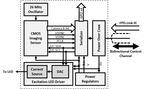
The CMOS imaging sensor PCB holds all the electronics needed to power and control the CMOS imaging sensor and excitation LED. A list of circuit features and components are listed below
- Power over coax filter to separate data/control stream from DC power.
- 3.3V and 1.8V power regulators.
- Red LED shows board is powered properly and can be used for animal tracking.
- Serializer interfaces with imaging sensor and packages data to be sent over coax.
- A Digital to Analog Converter (DAC) and constant current source are used to control and power the excitation LED.
Coaxial Cabling
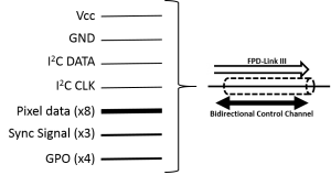
The head mounted scope is connected to the DAQ hardware through a single, lightweight coaxial (coax) cable.
50Ω Coaxial Cable Features
- Power over coax + control signals + data + GPO
- Down to 0.3mm diameter
- Up to 15m long
- Commutator compatible
- Addition 4 lines of GPO
- Supports 12bit pixel data
- Up to 1.4Gbps
Excitation LED PCB
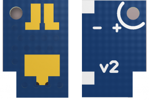
The excitation LED PCB is a simple 2 sided PCB with solder pads for a Luxeon SMD LED (P/N LXML-PB01-0030) and wires to power the LED. The PCB acts as a small heat sink and has a 1mm mounting hold for attaching it to the miniscope body. The LED is powered by a constant current source on the CMOS imaging sensor PCB and controlled through an 8bit DAC. We generally run this LED at only a few percent of it maximum power (3mA to 10mA current).
Mass of Head Mounted Scope Components
| Component | Mass (g) | Quantity per Scope | Total Mass | Notes |
|---|---|---|---|---|
| Main Body | 0.51 | 1 | 0.51 | |
| Focusing Slider | 0.48 | 0.8 to 1 | 0.38 to 0.28 | Bottom portion can be cut off to reduce weight. |
| Filter Cover | 0.11 | 1 | 0.11 | |
| Screw (3mm long 1mm diameter) | 0.025 | 3 to 7 | 0.075 to 0.175 | |
| Magnet | 0.012 | 3 | 0.036 | |
| Optical Filter Set (per 1mm x 1mm x 1mm of glass) | 0.0017 | 54 | 0.09 | |
| Achromatic Lens (5mm Diameter) | 0.15 | 1 | 0.15 | Varies slightly with different focal lengths |
| Half Ball Lens | 0.02 | 1 | 0.02 | |
| LED PCB (without LED SMD) | 0.07 | 1 | 0.07 | |
| LED SMD + Wires | 0.05 | 1 | 0.05 | |
| CMOS PCB (excluding CMOS sensor) | 0.85 | 1 | 0.85 | |
| CMOS Imaging Sensor | 0.76 | 1 | 0.76 |
- Total scope mass between 3g and 3.3g.
- Around 0.6g of the CMOS PCB comes from the circuitry and components needed to support power and data over a single coaxial cable. In our experience a very light, flexible cable is well worth the trade off of having the scope be 0.6g lighter.
- It is feasible to drop the scope's mass to under 3g with a little bit of work. It could be dropped closer to 2g if the bare die of CMOS imaging sensor was directly wire bonded to the PCB.

