Difference between revisions of "System Assembly"
(→Soldering LED power lines) |
Chrisl1026 (talk | contribs) (→Soldering Coaxial Cable to CMOS Imaging Sensor PCB) |
||
| (33 intermediate revisions by 6 users not shown) | |||
| Line 1: | Line 1: | ||
This guide will take you through the assembly of the entire miniscope system. | This guide will take you through the assembly of the entire miniscope system. | ||
| + | |||
| + | [[File:ScopeAssemblyParts.jpg|thumb|400px]] | ||
| + | |||
== Head Mounted Scope Assembly == | == Head Mounted Scope Assembly == | ||
A detailed video is soon to come. | A detailed video is soon to come. | ||
| Line 5: | Line 8: | ||
#Examine '''Main Body''' under a microscope and remove any plastic burrs and obstructions to the light paths. | #Examine '''Main Body''' under a microscope and remove any plastic burrs and obstructions to the light paths. | ||
#Press fit magnets into the 3 holes on the bottom of the '''Main Body''' making sure the polarity of the magnets match previously assembled scopes. | #Press fit magnets into the 3 holes on the bottom of the '''Main Body''' making sure the polarity of the magnets match previously assembled scopes. | ||
| − | #Slide the '''Achromatic Lens''' down the emission path until it sits flush against the aperture ring above the emission filter slot. Inspect fit under microscope and adjust if necessary. | + | #Slide the '''Achromatic Lens''' down the emission path until it sits flush against the aperture ring above the emission filter slot. The more curved of the two sides of the lens should face down toward the emission filter. Inspect fit under microscope and adjust if necessary. |
| − | #With the coated surface facing the incoming light, use forceps to slide the ''Excitation Filter, Dichroic Mirror, and Emission Filter''' into their respective slots until their sides are flush with the Main Body. The black edges of the filters represent which edges should be blackened. | + | #With the coated surface facing the incoming light, use forceps to slide the ''Excitation Filter, Dichroic Mirror, and Emission Filter''' into their respective slots until their sides are flush with the Main Body. The black edges of the filters represent which edges should be blackened (optional). |
#Place the '''Half-Ball Lens''' in spherical opening (optical glue is optional). Inspect under a microscope to make sure the lens surface is flush with the plastic. Screw the Excitation LED PCB in place using 1mm self-tapping screws. | #Place the '''Half-Ball Lens''' in spherical opening (optical glue is optional). Inspect under a microscope to make sure the lens surface is flush with the plastic. Screw the Excitation LED PCB in place using 1mm self-tapping screws. | ||
#Screw the '''Filter Set Holder''' onto the '''Main Body''' using 2 to 3 1mm self-tapping screws. | #Screw the '''Filter Set Holder''' onto the '''Main Body''' using 2 to 3 1mm self-tapping screws. | ||
| Line 15: | Line 18: | ||
<br clear=all> | <br clear=all> | ||
| − | === Filter Edge Blackening ( | + | {{#ev:youtube|https://youtu.be/p-RcVYbLlKc|640|center}} |
| − | + | ||
| + | <br clear=all> | ||
| + | |||
| + | === Filter Edge Blackening (NOT USUALLY NECESSARY) === | ||
| + | Our current version should not need this, but if you have light that leaks through the miniscope (i.e., you can see light being recorded even when the bottom of the miniscope is entirely covered), then blackening of the filters can fix this problem. We have noticed that if a scope has light leakage issues (excitation light making it to the CMOS imaging sensor) blackening the dichroic and emission filters' sides fixes the issue. | ||
Optical companies may be able to blacken the sides for you but it is also easy to do yourself. We have had the most success using Rustoleum Flat Black Enamel with a thin paintbrush. | Optical companies may be able to blacken the sides for you but it is also easy to do yourself. We have had the most success using Rustoleum Flat Black Enamel with a thin paintbrush. | ||
| Line 25: | Line 32: | ||
=== Soldering Coaxial Cable to CMOS Imaging Sensor PCB === | === Soldering Coaxial Cable to CMOS Imaging Sensor PCB === | ||
| − | {{#ev:youtube|https://youtu.be/ | + | {{#ev:youtube|https://youtu.be/AZvfDosYdxc|640|center}} |
| + | https://youtu.be/AZvfDosYdxc | ||
| + | |||
| + | === Soldering the solder-jumper on the bottom of the CMOS PCB (v3.2) === | ||
| + | If you are using version 3.2 of the CMOS imaging sensor PCB you will need to apply solder across the two half-circles on the bottom of the PCB. | ||
| + | |||
| + | [[File:CMOS_Short_v3_2.png|center|600px]] | ||
| + | |||
| + | === Soldering SMA Connector to Coaxial Cable === | ||
| + | Below shows the easiest way to solder an SMA connector to the end of the coaxial cable. This can also be done using standard SMA wire connectors but it is more difficult and more prone to breaks. '''Make sure to test for shorts in the coax cable before plugging in and powering up the DAQ PCB. If a short is present, permanent damage can be done to the DAQ PCB.''' | ||
| + | |||
| + | {{#ev:youtube|https://youtu.be/Jrn2oWERPpw|640|center}} | ||
| + | |||
| + | === Soldering LED to PCB === | ||
| + | {{#ev:youtube|8KWx6qv82ts|640|center}} | ||
| + | |||
| + | '''Removing the silicone cover of the LED:''' try to slowly peal it off in 1 piece and make sure not to touch the white square (illumination surface) with forceps. It is fine to leave a small amount of silicone attached to the LED as long as it does not extend much higher than the actual surface of the LED. | ||
=== Soldering LED power lines === | === Soldering LED power lines === | ||
[[File:LEDWire.png|thumb|300px]] | [[File:LEDWire.png|thumb|300px]] | ||
{{#ev:youtube|https://youtu.be/AWg9-qTKF1Y|640|center}} | {{#ev:youtube|https://youtu.be/AWg9-qTKF1Y|640|center}} | ||
| + | |||
| + | '''Soldering the LED wires to the LED PCB:''' Once the LED PCB is attached to the scope body, the wires running off the LED PCB need to fit through a thin slot cut out of the scope body. This slot is only the width of the 2 solder pads on the LED PCB so care should be taken to solder the wires directly on top of the solder pads and have the wires extend straight off the PCB. It is helpful to use relatively thin wires, ideally with and outer diameter of 0.5mm or less. | ||
=== Baseplate Assembly === | === Baseplate Assembly === | ||
| Line 39: | Line 64: | ||
== Data Acquisition System Assembly == | == Data Acquisition System Assembly == | ||
| − | |||
| − | === Through-hole component assembly === | + | === Note on version 3.x of the DAQ PCB === |
| + | If you have the newer version of the DAQ PCB (version 3.x) you can disregard the through-hole and coax cable connector soldering described below. The DAQ PCB v3.x comes fully soldered and just needs the EEPROM inserted and switch/jumper configuration set correctly. The coaxial cable from the head mounted scope will connect to the J4 (SMA connector closest to the center of the DAQ PCB) connector. | ||
| + | |||
| + | |||
| + | [[File:DAQv3_x.png|center|500px]] | ||
| + | |||
| + | === Through-hole component assembly for version 2.x of PCB (USUALLY NOT NEEDED) === | ||
If you decide to have the through-hole components assembled by an assembly house you can skip this section. Below is a picture highlighting the necessary through-hole components that need to be soldered in order for the DAQ PCB to function properly. | If you decide to have the through-hole components assembled by an assembly house you can skip this section. Below is a picture highlighting the necessary through-hole components that need to be soldered in order for the DAQ PCB to function properly. | ||
| − | [[File:DAQPCBThroughHole.png|center| | + | [[File:DAQPCBThroughHole.png|center|500px]] |
*Description of components | *Description of components | ||
| Line 53: | Line 83: | ||
**J3,4,5: SMA connectors used for GPIO pins | **J3,4,5: SMA connectors used for GPIO pins | ||
**J6: We currently solder a short coax cable with SMA connector to these pads. This will be updated soon to a replace this with a proper PCB footprint | **J6: We currently solder a short coax cable with SMA connector to these pads. This will be updated soon to a replace this with a proper PCB footprint | ||
| + | {{#ev:youtube|https://youtu.be/-BMkPaSKkk8|640|center}} | ||
| + | |||
| + | === Plugging in EEPROM === | ||
| + | Plug in the EEPROM into socket U5 making sure the orientation is correct (With the USB connector on the bottom the writing on the EEPROM should be right side up). | ||
| + | |||
| + | [[File:EEPROM_Ori.png|center|500px]] | ||
=== Setting Jumpers === | === Setting Jumpers === | ||
| Line 68: | Line 104: | ||
[[File:PowerJumper.png|center|500px]] | [[File:PowerJumper.png|center|500px]] | ||
| + | |||
| + | === Epoxy USB Connector === | ||
| + | If a USB cable is forced in or pulled out of the USB connector at an angle there is a chance the connector could get ripped off the PCB. While not necessary, we suggest adding epoxy between the USB connector housing and PCB to increase its mechanical stability and decrease the chances of damage. Care must be taken to avoid getting any epoxy inside the USB housing. | ||
== Cable Assembly == | == Cable Assembly == | ||
| − | The cabling between the head mounted scope and DAQ hardware is only a single coaxial cable. A coaxial, or coax, cable consists of an inner conducting wire surrounded by an insulating dielectric and then outer, generally grounded, shield. In our system the inner conductor carries power along with a data link and bidirectional control channel and the outer shield needs to be grounded. Our hardware dynamically adjusts for signal attenuation and small voltage drops across the cable but | + | The cabling between the head mounted scope and DAQ hardware is only a single coaxial cable. A coaxial, or coax, cable consists of an inner conducting wire surrounded by an insulating dielectric and then outer, generally grounded, shield. In our system the inner conductor carries power along with a data link and bidirectional control channel and the outer shield needs to be grounded. Our hardware dynamically adjusts for signal attenuation and small voltage drops across the cable but care should still be taken to minimize these loses. The videos above show how to solder the coax cable to the CMOS Imaging Sensor PCB and how to connectorize the other end with an SMA connector. Suggested cable can be found on our parts list but any coax cable with the properties listed below should work. |
Properties to look for in a coax cable are | Properties to look for in a coax cable are | ||
| Line 76: | Line 115: | ||
*Light weight and highly flexible. We like to use coax cables with an outer diameter of 1.5mm or less. It is important to note that as the diameter of the cable decreases, so does the length it can support. | *Light weight and highly flexible. We like to use coax cables with an outer diameter of 1.5mm or less. It is important to note that as the diameter of the cable decreases, so does the length it can support. | ||
*Handles bandwidths up to 1GHz. For short distances this requirement can be reduced. | *Handles bandwidths up to 1GHz. For short distances this requirement can be reduced. | ||
| + | |||
| + | == What to do After System Assembly == | ||
| + | [[Software and Firmware Setup]] | ||
| + | |||
| + | [[Initial Testing of Assembled Miniscopes]] | ||
Latest revision as of 13:51, 10 July 2018
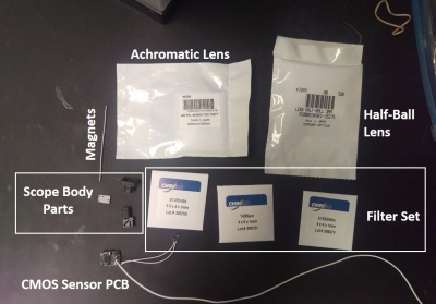
This guide will take you through the assembly of the entire miniscope system.
Contents
Head Mounted Scope Assembly
A detailed video is soon to come.
- Examine Main Body under a microscope and remove any plastic burrs and obstructions to the light paths.
- Press fit magnets into the 3 holes on the bottom of the Main Body making sure the polarity of the magnets match previously assembled scopes.
- Slide the Achromatic Lens down the emission path until it sits flush against the aperture ring above the emission filter slot. The more curved of the two sides of the lens should face down toward the emission filter. Inspect fit under microscope and adjust if necessary.
- With the coated surface facing the incoming light, use forceps to slide the Excitation Filter, Dichroic Mirror, and Emission Filter' into their respective slots until their sides are flush with the Main Body. The black edges of the filters represent which edges should be blackened (optional).
- Place the Half-Ball Lens in spherical opening (optical glue is optional). Inspect under a microscope to make sure the lens surface is flush with the plastic. Screw the Excitation LED PCB in place using 1mm self-tapping screws.
- Screw the Filter Set Holder onto the Main Body using 2 to 3 1mm self-tapping screws.
- Slide the Focusing Slider onto the Main Body. Make sure the two side holes have been tapped already with a 00-80 tap.
- Epoxy, screw, or rubber band the CMOS Imaging Sensor PCB onto the Focusing Slider orienting the LED wires to the side of the scope with the Excitation LED PCB.
Filter Edge Blackening (NOT USUALLY NECESSARY)
Our current version should not need this, but if you have light that leaks through the miniscope (i.e., you can see light being recorded even when the bottom of the miniscope is entirely covered), then blackening of the filters can fix this problem. We have noticed that if a scope has light leakage issues (excitation light making it to the CMOS imaging sensor) blackening the dichroic and emission filters' sides fixes the issue.
Optical companies may be able to blacken the sides for you but it is also easy to do yourself. We have had the most success using Rustoleum Flat Black Enamel with a thin paintbrush.
- Pour a few drops of the enamel into a plastic dish and let it sit out for a few minutes to thicken.
- Holding the sides of the filter with forceps carefully apply a thin layer of the enamel to the 2 sides not in contact with the forceps.
- Let dry for a few minutes before setting the filter down.
- Wait a couple hours for the enamel to dry further then repeat step 2 on the other 2 sides of the filter.
Soldering Coaxial Cable to CMOS Imaging Sensor PCB
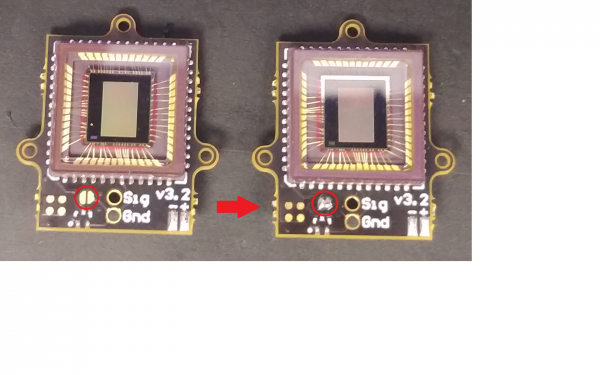
Soldering the solder-jumper on the bottom of the CMOS PCB (v3.2)
If you are using version 3.2 of the CMOS imaging sensor PCB you will need to apply solder across the two half-circles on the bottom of the PCB.
Soldering SMA Connector to Coaxial Cable
Below shows the easiest way to solder an SMA connector to the end of the coaxial cable. This can also be done using standard SMA wire connectors but it is more difficult and more prone to breaks. Make sure to test for shorts in the coax cable before plugging in and powering up the DAQ PCB. If a short is present, permanent damage can be done to the DAQ PCB.
Soldering LED to PCB
Removing the silicone cover of the LED: try to slowly peal it off in 1 piece and make sure not to touch the white square (illumination surface) with forceps. It is fine to leave a small amount of silicone attached to the LED as long as it does not extend much higher than the actual surface of the LED.
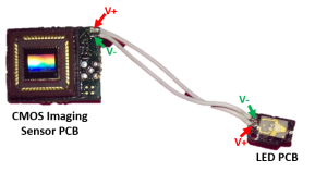
Soldering LED power lines
Soldering the LED wires to the LED PCB: Once the LED PCB is attached to the scope body, the wires running off the LED PCB need to fit through a thin slot cut out of the scope body. This slot is only the width of the 2 solder pads on the LED PCB so care should be taken to solder the wires directly on top of the solder pads and have the wires extend straight off the PCB. It is helpful to use relatively thin wires, ideally with and outer diameter of 0.5mm or less.
Baseplate Assembly
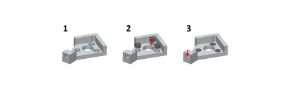
- Inspect Baseplate for burrs.
- Press fit the 3 magnets flush or slightly recessed into the Baseplate.
- Tap the set screw hole with a 00-80 tap.
Data Acquisition System Assembly
Note on version 3.x of the DAQ PCB
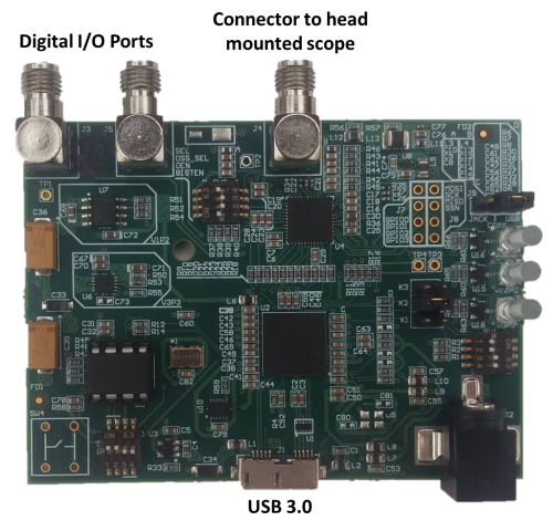
If you have the newer version of the DAQ PCB (version 3.x) you can disregard the through-hole and coax cable connector soldering described below. The DAQ PCB v3.x comes fully soldered and just needs the EEPROM inserted and switch/jumper configuration set correctly. The coaxial cable from the head mounted scope will connect to the J4 (SMA connector closest to the center of the DAQ PCB) connector.
Through-hole component assembly for version 2.x of PCB (USUALLY NOT NEEDED)
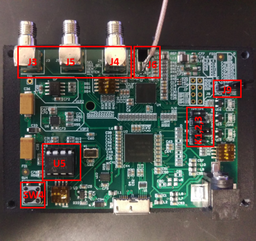
If you decide to have the through-hole components assembled by an assembly house you can skip this section. Below is a picture highlighting the necessary through-hole components that need to be soldered in order for the DAQ PCB to function properly.
- Description of components
- SW4: Reset button the resets can reset the USB Host Controller
- U5: EEPROM (memory that holds the DAQ firmware) socket. You can also solder the EEPROM IC directly to the board but I prefer using an IC socket so I can swap out the EEPROM if necessary
- K1,2,3: Each are 2pin 0.1" headers
- J9: A 3pin header used with a 2pin jumper to select power source for the microscope
- J3,4,5: SMA connectors used for GPIO pins
- J6: We currently solder a short coax cable with SMA connector to these pads. This will be updated soon to a replace this with a proper PCB footprint
Plugging in EEPROM
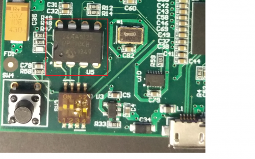
Plug in the EEPROM into socket U5 making sure the orientation is correct (With the USB connector on the bottom the writing on the EEPROM should be right side up).
Setting Jumpers
Once all SMD and through-hole components are in place the switches and jumpers need to be properly set for uploading firmware and powering the microscope.
Below shows the default configuration of the 3 SMD switches on the DAQ PCB.
Below shows the possible K1, K2, and K3 jumper configurations.
The scope power jumper, J9, sets the power source powering the head mounted scope. In most cases the USB power configuration should be used and no DC power supply needs to be hooked up the the DC jack on the PCB.
Epoxy USB Connector
If a USB cable is forced in or pulled out of the USB connector at an angle there is a chance the connector could get ripped off the PCB. While not necessary, we suggest adding epoxy between the USB connector housing and PCB to increase its mechanical stability and decrease the chances of damage. Care must be taken to avoid getting any epoxy inside the USB housing.
Cable Assembly
The cabling between the head mounted scope and DAQ hardware is only a single coaxial cable. A coaxial, or coax, cable consists of an inner conducting wire surrounded by an insulating dielectric and then outer, generally grounded, shield. In our system the inner conductor carries power along with a data link and bidirectional control channel and the outer shield needs to be grounded. Our hardware dynamically adjusts for signal attenuation and small voltage drops across the cable but care should still be taken to minimize these loses. The videos above show how to solder the coax cable to the CMOS Imaging Sensor PCB and how to connectorize the other end with an SMA connector. Suggested cable can be found on our parts list but any coax cable with the properties listed below should work.
Properties to look for in a coax cable are
- 50ohm impedance. This is absolutely necessary.
- Light weight and highly flexible. We like to use coax cables with an outer diameter of 1.5mm or less. It is important to note that as the diameter of the cable decreases, so does the length it can support.
- Handles bandwidths up to 1GHz. For short distances this requirement can be reduced.
