Difference between revisions of "Data Acquisition Box"
(→Overview) |
(→General Peripheral Interface) |
||
| (2 intermediate revisions by one other user not shown) | |||
| Line 38: | Line 38: | ||
== Firmware == | == Firmware == | ||
| + | The firmware image and firmware source code can be found at the [https://github.com/daharoni/Miniscope_DAQ_Firmware.git Miniscope DAQ firmware repository]. | ||
| + | |||
The firmware running the DAQ box consists of a USB descriptor, General Peripheral Interface (GPIF II) state machine, and ARM Cortex programming. All three of these components were written, and can be modified, using the Cypress EZ-USB FX3 SDK. The SDK also provides the needed software to flash the firmware onto the DAQ board through the USB connection. Below is a short description of the firmware components. | The firmware running the DAQ box consists of a USB descriptor, General Peripheral Interface (GPIF II) state machine, and ARM Cortex programming. All three of these components were written, and can be modified, using the Cypress EZ-USB FX3 SDK. The SDK also provides the needed software to flash the firmware onto the DAQ board through the USB connection. Below is a short description of the firmware components. | ||
| Line 44: | Line 46: | ||
=== General Peripheral Interface === | === General Peripheral Interface === | ||
| − | The General Peripheral | + | The General Peripheral Interface (GPIF II) configures the GPIOs of the USB Host Controller as well as defines the state machine for handling a raw video data stream. The GPIF connects to the parallel output of the imaging sensor as well as the imaging sensor's sync signals (Frame Valid, Line Valid, Pixel Clock) and the state machine defines how the imaging data gets packaged before being sent over the USB interface. |
=== ARM Cortex Programming === | === ARM Cortex Programming === | ||
| Line 51: | Line 53: | ||
== Guides and Tutorials == | == Guides and Tutorials == | ||
| + | [[System Assembly]] | ||
| + | |||
[[Software and Firmware Setup]] | [[Software and Firmware Setup]] | ||
Latest revision as of 15:07, 3 May 2017
Contents
Overview
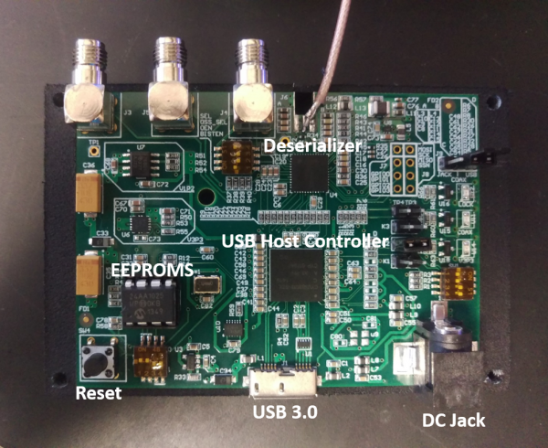
Design, fabrication, and assembly files can be found at the Miniscope DAQ PCB Github repository.
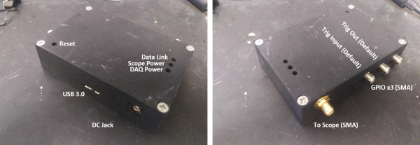
The Data Acquisition (DAQ) Box sits between the head mounted microscope and PC and mediates communication between the two. The DAQ box connects over super speed USB (USB3.0) to the PC and enumerates as a generic webcam using the USB Video Class (UVC) device protocol. This means that other open source or commercial webcam software should be able to control and stream data for the system. Below shows the default configuration of the DAQ hardware using the firmware provided on this wiki.
The PCB is roughly 3" x 2.25" and housed in a 3D printed box. The PCB is a 4 layer board with controlled impedance for the USB data lines.
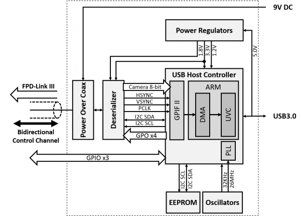
Below is the schematic of the DAQ hardware.
Connectors
Status LEDs
Jumper Settings
Switch and Boot Mode Settings
Firmware
The firmware image and firmware source code can be found at the Miniscope DAQ firmware repository.
The firmware running the DAQ box consists of a USB descriptor, General Peripheral Interface (GPIF II) state machine, and ARM Cortex programming. All three of these components were written, and can be modified, using the Cypress EZ-USB FX3 SDK. The SDK also provides the needed software to flash the firmware onto the DAQ board through the USB connection. Below is a short description of the firmware components.
USB Descriptor
The USB descriptor is based on the USB Video Class (UVC) descriptor structure which causes the DAQ board to enumerate as a generic webcam. The descriptor conveys supported configurations, frame size, ect. to the PC.
General Peripheral Interface
The General Peripheral Interface (GPIF II) configures the GPIOs of the USB Host Controller as well as defines the state machine for handling a raw video data stream. The GPIF connects to the parallel output of the imaging sensor as well as the imaging sensor's sync signals (Frame Valid, Line Valid, Pixel Clock) and the state machine defines how the imaging data gets packaged before being sent over the USB interface.
ARM Cortex Programming


